Highscore table – NodeJS

After starting the task in class, I have gone on to complete a highscore table that can be used to store anyone’s highscore and retrieve a list of them back. I wrote the server in NodeJS and used a MongoDB to store the data.

Creating the server with Node wasn’t too difficult as we used a thing called Express. That gives you a set up for a server and then you extend on it by having different routes for different pages. The functionality of the highscore table is a little limited due to time restraints, but it works well for a top 10. It allows a creator to store a user’s score, username and date into the database to be retrieved at anytime. When the data is to be retrieved, two parameters are required to be passed. First, the starting point of the rankings. This is so if you want to see maybe rank 10-20, you can ask for them. Secondly, you need to pass the amount of results you want back. That way, if for example you want the top 100, you ask for results starting at 0, and you want 100 results back.

I struggled with the MongoDB stuff as a few things from their website didn’t appear to work. I am certain I must have been using them wrong, because things such as .forEach was not working. However, I found other ways of doing it and after many trial and errors scenarios, I finally managed to get it all working together. The next step was to actually use this data in a different application that wasn’t the server. I decided I would do it in Unity.

Unity has a nice class called WWW built in that allows you to send and receive data from a server. This made it super simple to send data to be stored and ask for it back. I set up a few input boxes and buttons and then hooked them up to be able to send and receive data. I then display it on the screen to demonstrate it works. There were not too many issues with getting it to work in Unity. The largest issue come in how to format the data to send. Before using Unity with the server, I was using Postman to send Post requests. There, the body looked like this:

{“username”:”corey”, “score”:100}

However, I didn’t realise I had to send them separately in unity. So I was sending it as a single object and it was inserting it as one object, which was not desirable. Once I got past that, the other issue I had was sending an integer. As I am using the Greater than and Less than operations to send data back, they need to be ints. But when I sent the data (even as an int), it kept getting converted to a string. To fix this I had to parse the text on the server side. It looks for the score object and parses it to an int.
Dyadic got Greenlit!

Everytime I think about how we have earnt the right to release a game on steam, I get a little excited. Steam is THE place for PC gaming. It’s where my massive library of PC games is stores. It’s a place I check regularly to see what the most current specials are and to play my games. It’s pretty much the place you want to release your game on for PC.

I woke up on Friday the 14th of August to see this email in my inbox: “Congratulations, Dyadic has been Greenlit!”. At first I didn’t believe it. It was 6.30am, I was very tired, and I was very sceptical. I tried reading through the email, then just decided to open steam and check. And behold, it was actually true. I wasn’t half asleep anymore. I was messaging team members about it and we were celebrating. We were excited. We had achieved the Greenlit status.

This whole development cycle has been extremely interesting and different. I always knew there was a lot of work involved in creating a game. I have done so many times. However, I never really looked at it from different angles. Marketing is difficult and time consuming. Writing the devlogs takes time. And there are a load of questions we have to ask ourselves about marketing our game. It’s been hard, and none of us really knew if we were doing it right, but I guess we must have been doing something ok.

Not trying to sound too cliche but I am really thankful for all the support we have received. Being able to work on a games project that would be received by a large market is something I have dreamed of since I was about 12 and I decided I wanted to make games. I really want to put my all into this and hopefully something will come from it.

Green Banana

Green Banana is probably the best 2D game engine in existence if I do say so myself. How did it end up with such a silly name? Simple. I named the engine at 8.30am on a Monday morning before I had had any coffee that day.

The Green Banana Engine (GBE) was created as part of a 40 hour comp where you can make anything called “Make-A-Thing“. My team consisted of Chris Snitzerling (Programmer), Callan Syratt (Programmer), Angelica Zurawski (Artist) and Myself (Programmer). The crazy idea to make an engine in 40hours came from the fact that it doesn’t matter if we succeed or not, as long as we learn, and the fact that we really wanted to challenge ourselves.

The first day was a little chaotic. We had to come up with a game idea to show off the engine and we had to start UML for how the whole engine was going to work. The idea we settled on was a Marshmellow platformer. The Marshmellow would run through the level, collect coins, purchase upgrades, and avoid enemies. Generic, yes, but in the end we were lucky to even get that going.

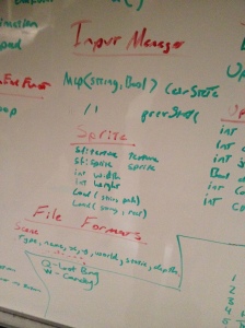
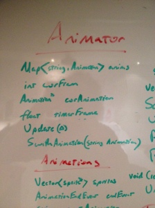
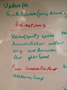
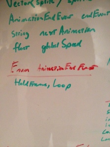
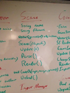
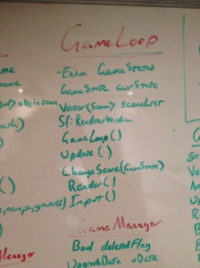
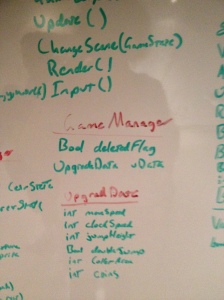
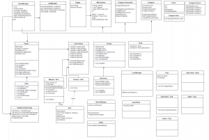
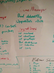
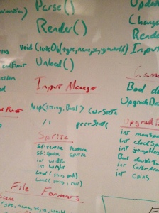
We spent about half of the first day and half of the second doing UML and planning how everything out fit together. This process was a lot determining what was needed in the engine, and then how we would do it. We stood at a board talking it over for hours on end, and eventually, we can to something that looked like it was going to work (but it totally wasn’t!). I would insert a picture of the Nicely done UML, but I cannot locate it at the moment. Instead, you get scribbles from a board.

IMG_0116 IMG_0117IMG_0118 IMG_0109 IMG_0110 IMG_0111 IMG_0112 IMG_0113 IMG_0114

After all the planning was done, we assigned work and got started. This is our favourite part. We all started writing stuff, committing it to the repo and then we start to realise things are not going to work. So we go back to the board and work out a solution. This happened for 2 days. Eventually we started testing stuff and it was working…mostly. Just don’t run the game for too long ;). Now that we had the systems implemented, it was time to make the game.

We had approximately a day to make the game. Needless to say, during this whole project, we didn’t just work at uni. We continued it at home each night or we stayed back at uni until it closed at like 6.30-7…so we sorta had more than 40hours. But meh, that’s not important. Making the game was a little more teadious than we intended it to be as some of the systems we not developed in ways we would have liked. As we were sorta C++ rookies, we ran into a few issues with syntax, so some things were done in terrible ways.

As we needed to make a level, we ended up making a ingame level editor. If you paused the game, you could press 1 through to 0 or Q through to P to create objects and place them. You could then save the level so it would be the same next time. An issue we had with this were moving enemies. If they were mid movement and we saved their position, they would start in the wrong place next time. So it was back to the board and we fixed it. This wasn’t the most beautiful editor ever, but it functioned. We made final version of the level for the game in the last hour. We were stripped for time.

The art in this game was beautiful. It definitely allowed us to feel better about our work as we had nice artwork to show off in the game. We had a little laugh when we received a walk animation with 90 frames. It was extremely smooth.

Overall, we were very proud of our work. We created an engine and a game all within a week. From planning to coding to showing it off, it was all done. We won some award, we went home happy, and we rested for the next week, getting prepared to go back to uni.


https://github.com/Silcoish/GreenBananas


On a side note, here is some UML

uml

Handsome Dragon Games website

I worked on yet another website this trimester. I’m starting to get a name for myself…

At the beginning of this trimester, after deciding what name we were going to use as a team (Handsome Dragon Games), we purchases the domain name and hosting. Then I was in charge of making the website. This task basically fell to me as I was the only one with web experience and we needed it done as soon as possible so we could start promoting ourselves.

At the beginning of each website I develop, I forget how much I hate the whole process. Websites was how I first got started with code and which spiked my interest in making games, but boy do I hate making them nowadays. There is just so much bullshit. I think I have identified why I hate web development, and found ways to make it better.

My main problem is I know PHP. So I made the website with PHP. I just don’t enjoy writing that at all, so it’s miserable. But recently I got involved with Node and I am enjoying that so much more. Next time I am on for making a website, I will use Node instead and see how that goes.

Another problem I have with web development is making a sytle. I planned out the style, created it from scratch with CSS (though I have discovered Less since then and will use that next time to make this a little less painful) and then found out that the colours didn’t work. So we spent about 4 hours as a team just changing the colours and seeing if they work. However, css doesn’t have variables (again, will use Less next time!), so it was super annoying having to change the colours. Sure, you can use Ctrl+F to find the colours, but then you got to edit them everywhere they are used. Eventually, we settled on colours even though no one is truly happy with them. I think the problem is the theme isn’t very good.  What I did was look at a few themes and tried taking the best things and putting them together. I don’t think that worked very well.

Now that I have some experience with Node and Less, i’m once again looking forward to making a website. I really want to see if this makes the process a lot better or there is something else that I am overlooking at the moment that makes me unhappy to make websites.

Dyadic’s Greenlight Debut

It’s finally time… time to put Dyadic on Greenlight. We have all been working extremely hard over the last two weeks to make sure everything is up to scratch to make sure our Greenlight campaign goes well. Admittedly, I have probably put a bit too much time into this over Studio, but this was really important to me and my team so I made that sacrifice.

We have been doing many things outside of making the game to make sure we are ready. Things such as making promotional material (Posters, Business cards and Website), creating the videos needed for the Greenlight page and lots of writing. It has been a really interesting experience as these are things I haven’t really been apart of when making a game. All other projects I have worked on have never come this far, and it’s exciting being in this position.

It’s a little scary thinking that we will be showing off our game and people will be able to leave all sorts of feedback. I’m looking forward to reading all that feedback (negative or positive) and hopefully being able to shape the game that we want to make and that people want to play.

Everything was ready in time and the game was placed on Greenlight successfully. We didn’t miss anything vital, so that’s a good start. Now we need to continue marketing the game and getting lots of people onto that page voting for us. Within the first day we had a massive hit due to all the followers we have acquired through social media and lots of people sharing our page and post about greenlight. It was really motivating scrolling down facebook and seeing how many people actually cared enough about us and our project to share us. Let’s hope this all works out for the best.

OpenGL life

I got stuck into learning how opengl works over the last week. Thankfully, I wasn’t alone on this endeavour. Pat managed to help me a few times when I got confused for stuck. So thanks for that Pat!

I followed along the tutorials on open.gl. I decided to use SDL for creating the window and opengl context and glew to obtain all the function pointers needed for opengl. Unfortunately, I had more trouble setting up SDL and glew than I would like to admit. I downloaded SDL and set up the lib and include folder. I linked them within Visual Studios and I was getting linking errors. After a little looking through the lib folder, I realised I set the additional dependencies to SDL.lib and SDLmain.lib when they actually needed to be SDL2.lib and SDL2main.lib. No biggie, I found the problem fast enough. However, the next problem stumbled me a lot more. I knew I needed to move the dll files into the project directory, but for some reason, it didn’t work like it normally does. Normally I can place the dlls next to the .vcxproj file and Visual Studio will have no issue finding it. However, this time to run it in VS I had to add them to both the Release and Debug folders. I placed these files around everywhere and eventually it worked. Now I know for future reference how to solve this issue and where to put the files.

GLEW was also a bit of an issue. Not as big of an issue, but I still ran into one problem. When I set all this up, the glew website was down for maintenance. Luckily, I already had the files downloaded from when I used them a couple of months ago. So I put all the files needed into the include and lib directors, move the dlls into the Release and Debug folder and set the Dependencies of glew32.lib. However, it was still having issues. I spent a few minutes looking through all my settings and checking the files were in the correct folders and then I remembered I needed to add the dependencies opengl32.lib. Once I added that, it finally built and I had a black window that stayed open for 1 whole second and then closed. Progress was made.

I followed along and I learnt how to make an opengl context, initial glew to get opengl function pointers, and create the Vertex Buffer Object. I even understood a large proportion of how the rendering pipeline works. Then I got to shaders… The tutorial is a little vague here, as they never talk about the most popular ways of writing shaders, and they didn’t really explain you have to parse the shader. I decided I want to have .shader files (because they sound cool) with both the vertex and fragment shader in one. The way I establish where the vertex shader and fragment shader start is with #vert and #frag at the beginning of the shader.

My parser went through a few iterations, starting with it opening the file, looping through it line by line, checking if the line contains #vert or #frag and then adding the lines to the specified shader source. However, this wasn’t really a good way of doing it as it was potentially doing two finds each line of the file. The final iteration is it’s own class that has a shaderId which is just the program GLuint. It loads the whole file into memory then does 2 finds to find the position of #vert and #frag. Once they have been found, the source is created by getting a substring between the opening tag and the next tag (or the end of the file). This way there only needs to be 2 finds instead of a potential of 2 each line. In my shader class I made a large mistake which actually effected the end result not rendering. But more on that a bit further down.

Next I learnt about setting attributes for the shader and uniforms. These were simple enough as I understood the concepts from using shaders within Unity before. This is where I ran into one of the large problems. I was creating the Vertex Array Object but it was crashing everytime. I tried moving the code around and still nothing. It turned out I had to do glewExperimental = true before I initiated glew. It appears that not everything is set up unless you have that line. Once that was done, I thought it was all good, I ran it and … nothing. To be expected. Now I will outline the other issues I had.

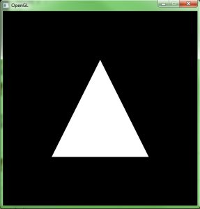
In my shader class, for the fragment shader, I forgot to change it glCreateShader(GL_FRAGMENT_SHADER); I left it as GL_VERTEX_SHADER for the fragment. The next issue was a silly one. When I was drawing the rectangle, I wrote the code on the wrong line and it was just outside of the core loop. Oopss. I picked up on that one fast luckily. The last major issue was I forgot to enable the program. I knew I had to do it too because I created functions in the Shader class to enable and disable. I just forgot to call it. Once that was all done, it finally drew a triangle. I was so happy because in totally this took me about 8 hours to write and understand what was going on. I didn’t want to just copy paste code, I wanted to actually understand. And I can say, I understand a lot more than I did before. Obviously it didn’t ALL stick the first time, but continuous use will help with that. I also changed the color uniform to be a random colour each update… so that looks cool. Anyway, here are my precious pictures:

HappiestDayOfMyLifeImCreativeISwear

R vs Processing

We have been tasked with showing visual data from a flocking simulation so that someone can tweak variables that affect the way the simulation runs with some insight. Suggestions were things such as spitting out a CSV and making graphs in Excel and Heatmaps. I will be completing Heatmaps, but instead of graphing in Excel, I decided I would look into R and Processing.

After doing a bit of research on both, I found a useful video on how to make a graph in R, so I took that option first. I downloaded and installed R, got myself an IDE (R studio) and started playing around with R. The way you run R in the IDE is different to anything I have done before. It only runs lines that are highlighted, mean you can run a single line in your program or you can highlight it all and run the whole application.

I downloaded a library for R called ggplot2. This library was created to easily plot data from a table. To create the table, I loaded in a CSV. Reading CSVs in R is so simple. They have a function specifically for reading them in, and once you have the table, to get data from a specific cell you just have to write the variable name then the heading or index next: table$heading1.

After creating a bar graph, I ran into my first problem. This was running in the IDE and was only showing one Graph at a time. So I decided to try and export the program to see what it does as a .exe…. however, that isn’t an option (as far as I could tell). All solutions I found said you could write another program to launch your R code as it’s an interpretive language, but you also need R installed on the deployment machine. This was the biggest killer as I plan on running this on Uni Computers where R isn’t installed. There is also the fact that I would never want to ask people to install R just to see some graphs that could have been done (and probably nice looking) in Excel. That leaves Processing.

Before even diving into finding libraries for processing that make graphs, I determined if you could export it as an .exe. And you can! So this is off to a good start. Another really good thing about processing is you don’t need to install it, so it can be ran anywhere. You just need the .exe you download and you are good to go.

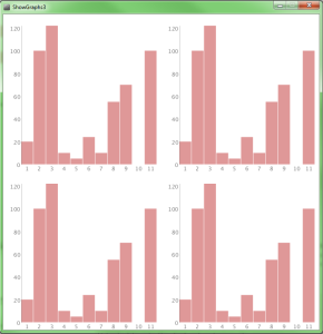
After a bit more research through all the libraries, I found once called giCenterUtils. It seemed to do exactly what I wanted, so I pulled the library into processing, and tried it out. I parsed my CSV file and passed all the lifetimes of the prey to a barchart. Then I specified where I wanted it and voila, there is a nice bar graph on my screen. The following picture shows the lifetimes of the prey in a bar graph form then displayed 4 times. That way once I have recorded more data, I will be able to show various plots on the screen.

Processing

My plan from here is to add titles to the graphs then have arrows on the sides of the screen so you can go between the graphs, allowing for more than 4 graphs to be shown.

Network Draw Application

I have really enjoyed this task a lot.

At the very end of week 1, we started talking about networking in class. It was all new stuff to me, so I found it extremely interesting. I have been interested in getting started with this stuff for a little. I did dip my toes into it back in Make-a-Thing last year, but I had some help from Pat.

The task we were given was to create a drawing application that would connect to a server (provided) and would allow multiple people to all draw together. We are able to send circles, squares, lines and single pixels to the server. I mainly focused on pixels as I wanted players to have that freehand drawing functionality.

I grabbed SFML 2.3 and linked it with a new project (I’m getting pretty good at this…) and got started. Then I got started. One of my goals for this project was to try and keep my project tidy and code in relevant files. I feel like I have achieved that well as all my networking code has gone into it own file, UI stuff into another etc. You can view the files on github.

My original idea for sending packets would be I have two arrays the size of SCREENSIZE * SCREENSIZE. Each one would represent a single pixel. Then, every interval, I would check the difference between them and send the pixel packets. I thought that would work well and I implemented it…overlooking a crucial thing. You can never draw over pixels. So…that was a problem. Also, it was difficult to send multiple pixels at once without being in-efficient.

After learning that it was possible to send multiple pixels in a single packet (and advised due to the overhead of each packet being so large for such a small amount of data), I changed the system. Instead, I created an array that would hold all the pixels to send each interval and when it was time to send the pixel packets, I would send the array instead, making that I would need to send way less packets, and also i’m not sending tiny amounts each time. This was much more efficient and I found on average I was sending 10x less packets.

I also worked on a few UI elements. So I created Buttons, Text Input Fields and Sliders. I thought that it would be worth investing time into these as I can use them in the future. The one I had most difficulty with was the text input field. The reason being was I didn’t understand how strings worked well enough. There was also an issue here with unicodes. Eventually, I realised strings are just an array of characters, and I worked through with the unicode characters. After much tinkering, I finally got a field where when you click on it, you can change the text, add more text and if you click out or press enter, it no longer has focus. I ended up using that so the user can type the IP and Port then having a connect button. The sliders were used for RBG.

The final task was to make a heatmap. I decided to map the user’s mouse position rather than when they click. To do this, I had a heatmap class that had an array to keep track of previous mouse positions. Similarly to the sending of packets, ever x interval, I would loop through the array and modify the image. I ran into a silly problem with this. It wasn’t drawing the pixels correctly and it was creating lots of images really fast. What was happening was the image was being saved and opened too fast, causing issues. This happened because I forgot to reset the interval. It was a really silly mistake and I laughed when I found it.

In the end, I was really happy with my draw client. I am really looking forward to doing so much more with it. There is a part two to this task that got completed over the next week. My understanding of networking is a lot stronger, and I believe this is an area in programming that I would like to focus on, alongside tools.

Link to github: https://github.com/Silcoish/studio3drawclient

Making a Raytracer Multi-Threaded

Recently we were given an un-optimized raytracer so we could work on making it multi-Threaded and some optimization techniques. During my time working with this project, I spent a lot of time trying to understand what multithreading is and how it works.

During the classes I asked lot of questions to help further my understanding. I feel like I have a good grasp of the concept now, allowing me to implement it into the raytracer and actually understand what is happening.

I used openmp for multithreading for the project. When I first got the project, it took ~64 seconds to render. By the end, I got it down to ~11. I would like to continue further with this in the future, but at the moment, I am focusing on other projects.

One problem I ran into while working was that you had to enable openmp. I was implementing it without seeing any effects. This signalled a red flag to me, so I researched it a bit and found out that you had to enable it within visual studios. Once that was done, the program was running much much faster.

What I did was use openmp to determine how many processors the computer had and based everything off that. To do that, it was one simple function:

unsigned int nProcessors = omp_get_max_threads();

Once that was complete, I was able to tell openmp to create threads equal to 4 times the amount of cores the computer had. I did that with:

omp_set_num_threads(nProcessors * 4);

I came to the number of threads by trial. I found that it was much faster to have double the amount of processors rather than the same amount. Then I kept increasing it, with it peaking at around 4 times the amount. Anything more and it was slowing down due to the excess time required to keep swapping threads.

The next process was the utilise multithreading. To do so, at loops where the program can run in parallel, I used:

#pragma omp parallel for

This broke the for loop down and assigned work to each different thread. An example of that is if there was a for loop like so:

for(int i = 0; i < 100; i++)

and there is four threads, it will assign the work load equally. The first thread will compute from 0 -24, the second thread will do 25-49 and so on. Then they can all run parallel making the program run much faster. At this point, the program was running at ~16 seconds.

In the way of optimisation, I didn’t really do too much. The main thing I did was think about how shadows were handled. I realised that when doing intersections to determine where the shadows were, if it intersected with one thing, then we knew we would have to cast shadows. Therefore, rather than loop through all the rest of the checks, I just returned form the function. Upon comparison of the old and new versions of the rendered images, there were no differences.

Overall, I feel like with this project, I have achieved a much better understanding of how threads work. I managed to do a little optimization appart from the threads and got it to render in ~11 seconds rather than the original ~64 seconds.

Link to raytacer: https://github.com/Silcoish/studio3raytracer

Creating Shapes using Vertices and Triangles (Research task)

I did some research over the weekend into voxel terrains (as I wanted to make a terrain gen tool) and I started getting into creating primitive shapes by specifying the vertices and triangles. When writing my tool, I didn’t want to have to the player specify a cube gameobject, instead, I decided it would be better to create the cube in code.

void CreateCube()
{
cube = new GameObject("Voxel");
cube.AddComponent();

Mesh mesh = new Mesh();

mesh.Clear();
mesh.name = "Custom Cube";
mesh.vertices = new Vector3[] { new Vector3(0, 0, 0), new Vector3(0, 1, 0), new Vector3(1, 1, 0), new Vector3(1, 0, 0), //front
new Vector3(1, 0, 1), new Vector3(1, 1, 1), new Vector3(0, 1, 1), new Vector3(0, 0, 1), //back
new Vector3(0, 1, 0), new Vector3(0, 1, 1), new Vector3(1, 1, 1), new Vector3(1, 1, 0), //top
new Vector3(0, 0, 1), new Vector3(0, 0, 0), new Vector3(1, 0, 0), new Vector3(1, 0, 1), //bottom
new Vector3(0, 0, 1), new Vector3(0, 1, 1), new Vector3(0, 1, 0), new Vector3(0, 0, 0), //left
new Vector3(1, 0, 0), new Vector3(1, 1, 0), new Vector3(1, 1, 1), new Vector3(1, 0, 1)}; //right
mesh.triangles = new int[] { 0, 1, 2, 0, 2, 3, 4, 5, 6, 4, 6, 7, 8, 9, 10, 8, 10, 11, 12, 13, 14, 12, 14, 15, 16, 17, 18, 16, 18, 19, 20, 21, 22, 20, 22, 23};

cube.GetComponent().mesh = mesh;

//apply material
Shader shader = Shader.Find("Diffuse");
Material mat = new Material(shader);
cube.GetComponent().sharedMaterial = mat;

cube.GetComponent().sharedMesh.RecalculateNormals();
}

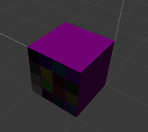
To explain the above code: I am using the bottom left as (0, 0, 0). From there, I am placing the vertices in relation to that point. So, there needs to be 8 vertices in total to make a cube (4 for the bottom, 4 for the top). Once I have created all the vertices, I need to move onto making triangles to render the faces. Each side of the cube requires two triangles, to make a square. Therefore, we need 8 triangles too. Triangles are made by specifying the order of vertices which join together. The first triangle is made for the bottom face and joins the points 0, 1, 2 (bottom left, top left, bottom right). Then to make the square, I made another triangle using the vertices 0, 2, 3 (bottom left, top right, bottom right). That will then create a square. Just repeat that for all the sides, and you now have a mesh. Just apply the mesh and ta-da! You got a cube!

When searching, I found it was fairly simple to create a cube by defining the vertices. I worked that out pretty simply, but then I ran into a problem with the triangles. I found that I was doing the vertices in different orders on each side, which would mean the triangles would need to be in different orders to make sure they are rendered from the correct side. After playing around for a while, I found that adding the triangles in a clockwise order will cause the triangle to render upwards, while adding them in a counter-clockwise order will render them downwards. This was interesting to learn as I was struggling with the faces rendering the wrong way.

CubeInUnity

I wanted to make sure that I actually did understand how all this worked, so I decided to create something more complicated: A Hexagonal Prism.


void CreateHexagonalPrism()
{
GameObject hexagonalPrism = new GameObject("HexagonalPrism");

Vector3[] verticies =
{
//Bottom vertices
new Vector3(0, 0, 0),
new Vector3(0.25f, 0, -0.5f),
new Vector3(0.5f, 0, 0),
new Vector3(0.75f, 0, -0.5f),
new Vector3(1, 0, 0),
new Vector3(0.75f, 0, 0.5f),
new Vector3(0.25f, 0, 0.5f),

//top vertices
new Vector3(0, 1, 0),
new Vector3(0.25f, 1, -0.5f),
new Vector3(0.5f, 1, 0),
new Vector3(0.75f, 1, -0.5f),
new Vector3(1, 1, 0),
new Vector3(0.75f, 1, 0.5f),
new Vector3(0.25f, 1, 0.5f)
};

int[] triangles =
{
//bottom
1, 2, 0,
3, 2, 1,
4, 2, 3,
5, 2, 4,
6, 2, 5,
0, 2, 6,

//top
7, 9, 8,
8, 9, 10,
10, 9, 11,
11, 9, 12,
12, 9, 13,
13, 9, 7,

//sides
0, 7, 1,
1, 7, 8,
1, 8, 3,
3, 8, 10,
3, 10, 4,
4, 10, 11,
4, 11, 5,
5, 11, 12,
5, 12, 6,
6, 12, 13,
6, 13, 0,
0, 13, 7
};

MeshFilter filter = hexagonalPrism.AddComponent<MeshFilter>();
hexagonalPrism.AddComponent<MeshRenderer>();

filter.mesh.Clear();
filter.mesh.vertices = verticies;
filter.mesh.triangles = triangles;

hexagonalPrism.transform.position = Vector3.zero;
}

In the code above, I did similar to the cube, but this required many more vertices and triangles. To begin with, I created all the vertices for the bottom of the hexagonal prism. Then I copied them all and shifted them up 1 unit. The order I created the vertices is:

HexagonOrder


I am unsure if this is how it would normally be done, but this made the most sense to me at the time, so I went with it. I made sure that when making the triangles for the bottom, I did it in reverse order to make sure they were facing down. Finally, I then joined the top and bottom up by using two triangles for each side of the shape. That required 12 triangles as there is 6 sides. Here is the finished product:

HexagonalPrisimInUnity


Overall, I feel like I understand how meshes are created a lot better. I plan to make more shapes that unity doesn’t naturally support in the coming days and then add them all to the GameObjects section so I can easily create them at will.